Bilateral Craneometric Landmarks
Alare
Abbreviation: al L / al R
Type: Alare is a bilateral Type III, hard tissue craniometric landmark.
Definition
According to Caple and Stephan (2015).
Alare is instrumentally determined as the most lateral point on the nasal aperture in a transverse plane.
Procedure
Use the frontal view to locate alare. For a better location zoom in the area of the piriform aperture. As a reference to determine the most lateral point of the piriform aperture we can use the vertical auxiliary line so that it contacts the edge of the aperture in the area of maximum opening. The horizontal auxiliary line will serve as a reference for the transverse plane. For a better fit we can use the lateral view to determine the maximum aperture. Follow the same procedure for the contralateral point.
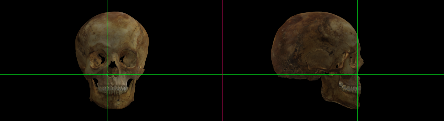 Fig. 1. Alare (right) on a skull 3D model in Norma Frontalis and Norma Lateralis.
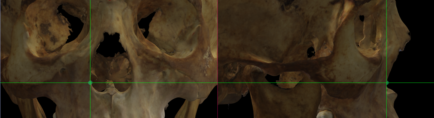 Fig. 2. Magnified image showing Alare (right) on a skull 3D model in Norma Frontalis and Norma Lateralis.
Observations
The inaccurate 3D skull acquisition and/or the specific features not properly scanned at the nasal region, such as the piriform aperture borders can difficult or make impossible the location of alare.
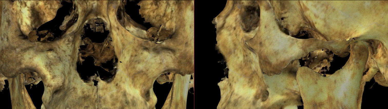 Fig. 3. Magnified image showing an innacurate scanned piriform aperture region in Norma Frontalis (left) and Norma Lateralis (right).
Asterion
Abbreviation: ast L / ast R
Type: Asterion is a bilateral Type I, hard tissue craniometric landmark.
Definition
According to Caple and Stephan (2015).
Asterion is the point located on the intersection of the parietal, temporal, and occipital bones.
Procedure
Use the flip button to change the Norma Frontalis view to the Norma Occipitalis view. Asterion can be located on the occipitalis and lateral view. For a better location zoom in the area of the intersection of the parietal, temporal, and occipital bones. Use the reference lines to determine the intersection of the lamboid, temporo-parietal and temporo-occipital sutures. Follow the same procedure for the contralateral point.
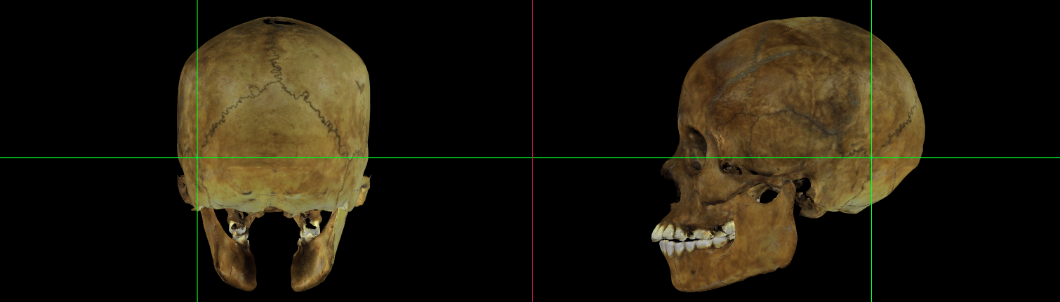 Fig. 4. Asterion (left) on a skull 3D model in Norma Occipitalis and Norma Lateralis.
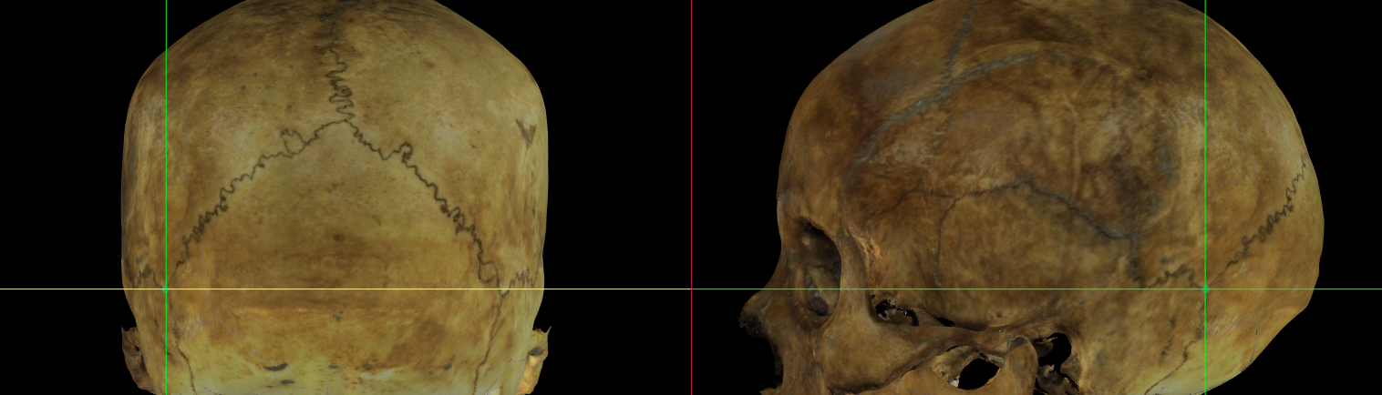 Fig. 5. Magnified image showing Asterion (left) on a skull 3D model in Norma Occipitalis and Norma Lateralis.
Observations
If sutures are indistinct or include Wormian bones, extend the lamboid suture onto its surface, and then extend the other two sutures (temporo-parietal, temporo-occipital) to the first line, finding asterion as the point midway between the intersections (Howells, 1973; Martin and Knussmann, 1988).
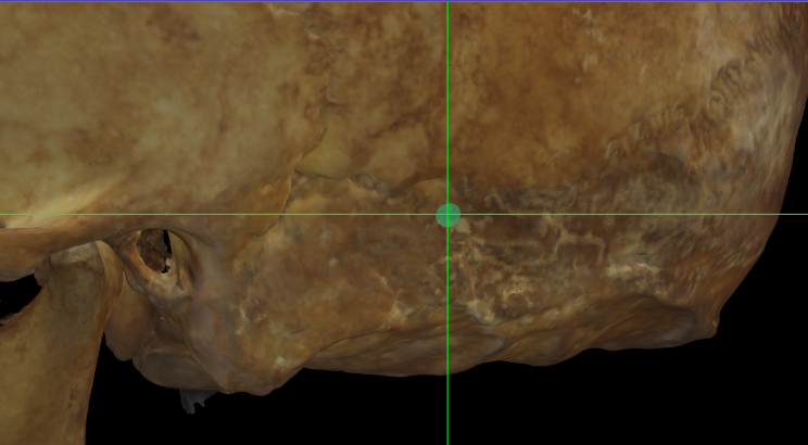 Fig. 6. Magnified image showing Asterion (left) on a skull 3D model with low definition of the sutures in Norma Lateralis.
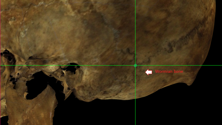 Fig. 7. Magnified image showing Asterion (left) on a skull 3D model with a Wormian bone in Norma Lateralis.
Auriculare
Abbreviation: au L / au R
Type: Auriculare is a bilateral Type II, hard tissue craniometric landmark.
Definition
According to Caple and Stephan (2015).
Auriculare is on the zygomatic root, vertically above the centre of the external auditory meatus.
Procedure
Use the lateral view to locate auriculare. For a better location zoom in the area of the zygomatic arch at the level of the external auditory meatus. As a reference of the centre of the external auditory meatus use the vertical auxiliary line. The horizontal line must be placed over the zygomatic arch root. Follow the same procedure for the contralateral point.
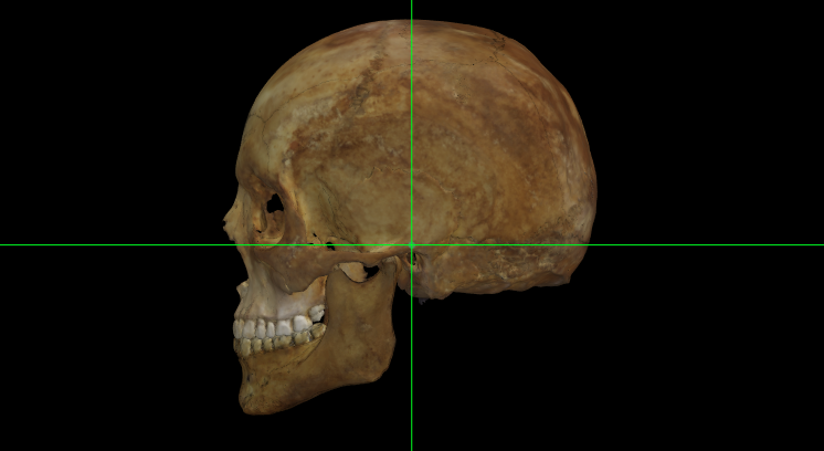 Fig. 8. Auriculare (left) on a skull 3D model in Norma Lateralis.
 Fig. 9. Magnified image of Auriculare (left) on a skull 3D model in Norma Lateralis.
Coronale
Abbreviation: co L / co R
Type: Coronale is a bilateral Type III, hard tissue craniometric landmark.
Definition
According to Caple and Stephan (2015).
Coronale is located at the most lateral point on the coronal suture
Procedure
Coronale can be located on the top view. For a better location zoom in the area of the coronal suture. As a reference use the vertical auxiliary line to determine the most lateral point of the skull at the level of the coronal suture. The horizontal line must be placed over the suture. Follow the same procedure for the contralateral point.
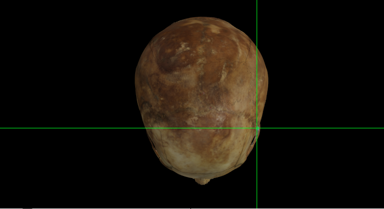 Fig. 10. Coronale (left) on a skull 3D model in Norma Verticalis.
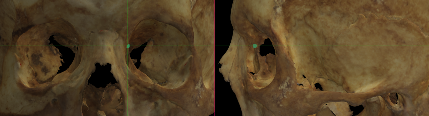 Fig. 11. Magnified image of Coronale (left) on a skull 3D model in Norma Verticalis.
Dacryon
Abbreviation: d L / d R
Type: Dacryon is a bilateral Type I, hard tissue craniometric landmark.
Definition
According to Caple and Stephan (2015).
Dacryon is the point on the medial border of the orbit where the lacrimomaxillary suture meets the frontal bone. There is often a small foramen at this point.
Procedure
Dacryon can be located on the frontal and lateral view. For a better location zoom in the area of the lacrimal bone. For a better visualization of the lacrimomaxillary suture we recommend using the lateral view. Use the horizontal auxiliary line as a reference to determine the area of intersection of the lacrimomaxilary suture with the frontal bone. Follow the same procedure for the contralateral point.
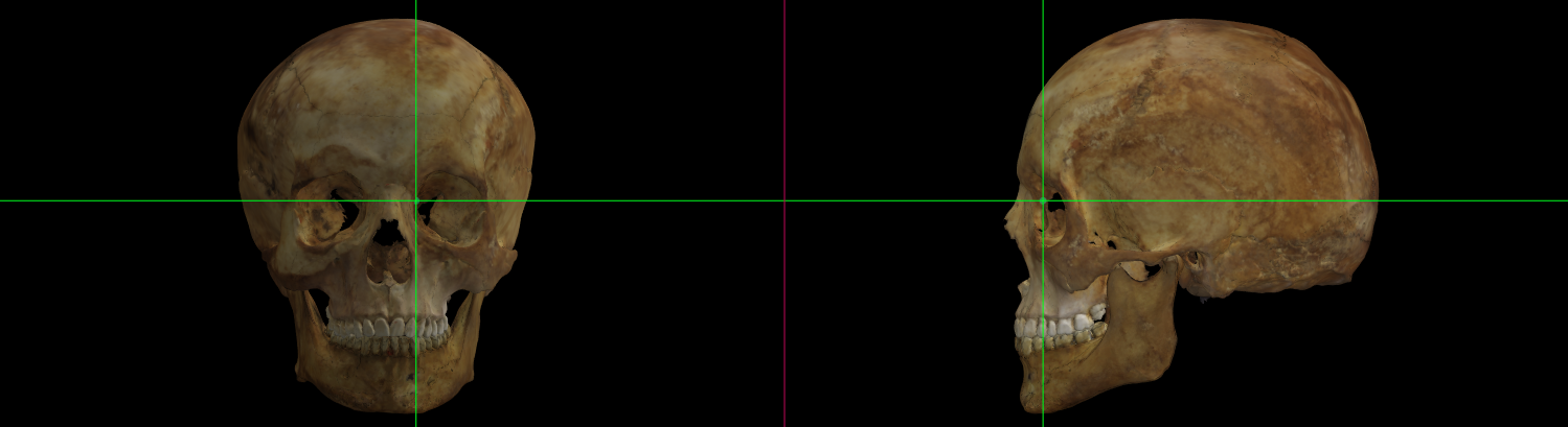 Fig. 12. Dacryon (left) on a skull 3D model in Norma Frontalis and Norma Lateralis.
Fig. 13. Magnified image showing Dacryon (left) on a skull 3D model in Norma Frontalis and Norma Lateralis.
Observations
If the lacrimomaxillary suture cannot be found, dacryon is aligned with the apex of the lacrimal fossa. If the apex is inferior to the frontal bone, a line should be extended superiorly from the apex to the frontal, and the point should be marked on the frontal (Howells, 1973).
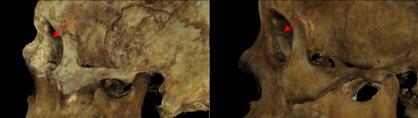 Fig. 14. Magnified image showing the left orbit on a skull 3D model in Norma Lateralis. At the left skull, the lacrimomaxillary suture is practically imperceptible while on the right skull it is well defined.
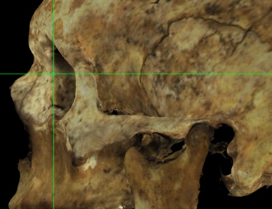 Fig. 15. Magnified image showing the estimated Dacryon (left) on the apex of the lacrimal fossa on a skull 3D model in Norma Lateralis.
Ectoconchion
Abbreviation: ec L / ec R
Type: Ectoconchion is a bilateral Type II, hard tissue craniometric landmark.
Definition
According to Caple and Stephan (2015).
Ectoconchion is the lateral point on the orbit at a line that bisects the orbit transversely.
Procedure
Ectoconchion can be located on the frontal view. For a better location zoom in the area of the corresponding orbit. Use the horizontal auxiliary line as a reference of a transvere plane that bisect the orbit into two equal halves. The vertical line must be located on the lateral border of the orbit. Follow the same procedure for the contralateral point.
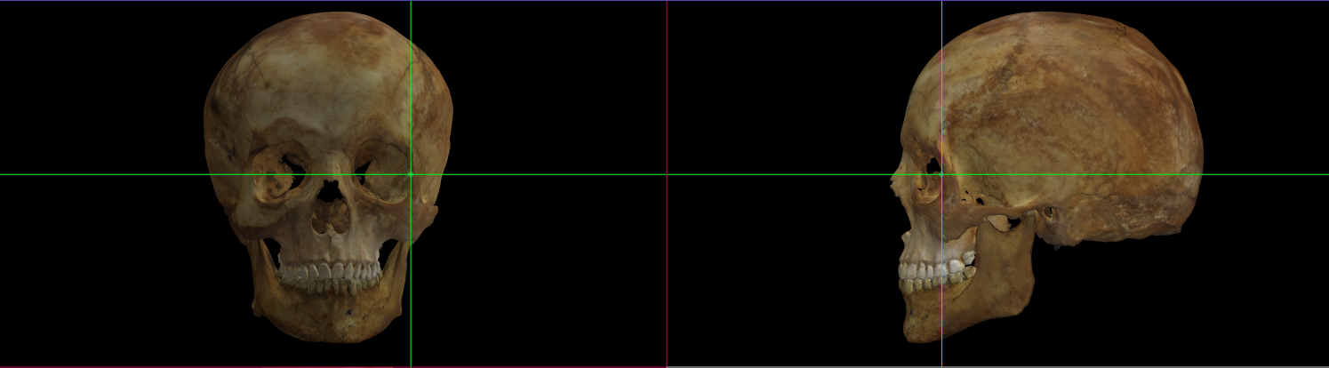 Fig. 16. Ectoconchion (left) on a skull 3D model in Norma Frontalis and Norma Lateralis.
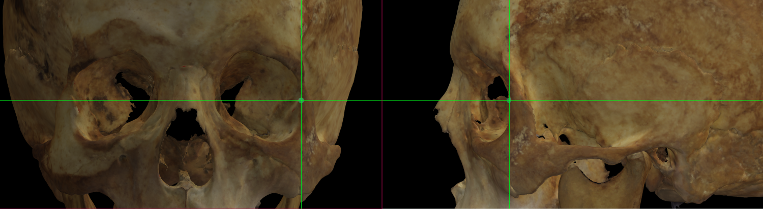 Fig. 17. Magnified image showing Ectoconchion (left) on a skull 3D model in Norma Frontalis and Norma Lateralis.
Ectomolare
Abbreviation: ecm L / ecm R
Type: Ectomolare is a bilateral Type III, hard tissue craniometric landmark.
Definition
According to Caple and Stephan (2015).
Ectomolare is positioned at the most lateral point on the lateral surface of the alveolar crest. Found along the second molar on the maxilla.
Procedure
Ectomolare can be located on the lateral view. For a better location zoom in the area of the second maxillary molar. Use the horizontal auxiliary line as a reference over the alveolar margin of the second molar and the vertical line to determine de midline of the molar. Follow the same procedure for the contralateral point.
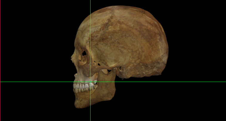 Fig. 18. Ectomolare (left) on a skull 3D model in Norma Lateralis.
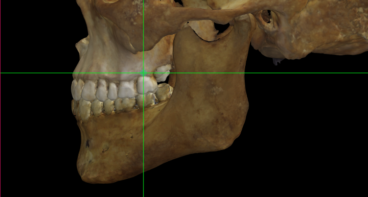 Fig. 19. Magnified image showing Ectomolare (left) on a skull 3D model in Norma Lateralis.
Observations
This point is generally positioned on the alveolar margin of the second maxillary molar (Martin and Knussmann, 1988).
Frontomalare anterior
Abbreviation: fma L / fma R
Type: Frontomalare anterior is a bilateral Type III, hard tissue craniometric landmark.
Definition
According to Caple and Stephan (2015).
Frontomalare anterior is the most anterior projecting point on the frontomalare suture (different from the frontomalare orbitale and temporale).
Procedure
Frontomalare anterior can be located on the lateral view. For a better location zoom in the area of the corresponding orbit. Use the vertical auxiliary line as a reference to determine the most anterior point of the frontomalare suture and the horizontal line as a reference over the suture. Follow the same procedure for the contralateral point.
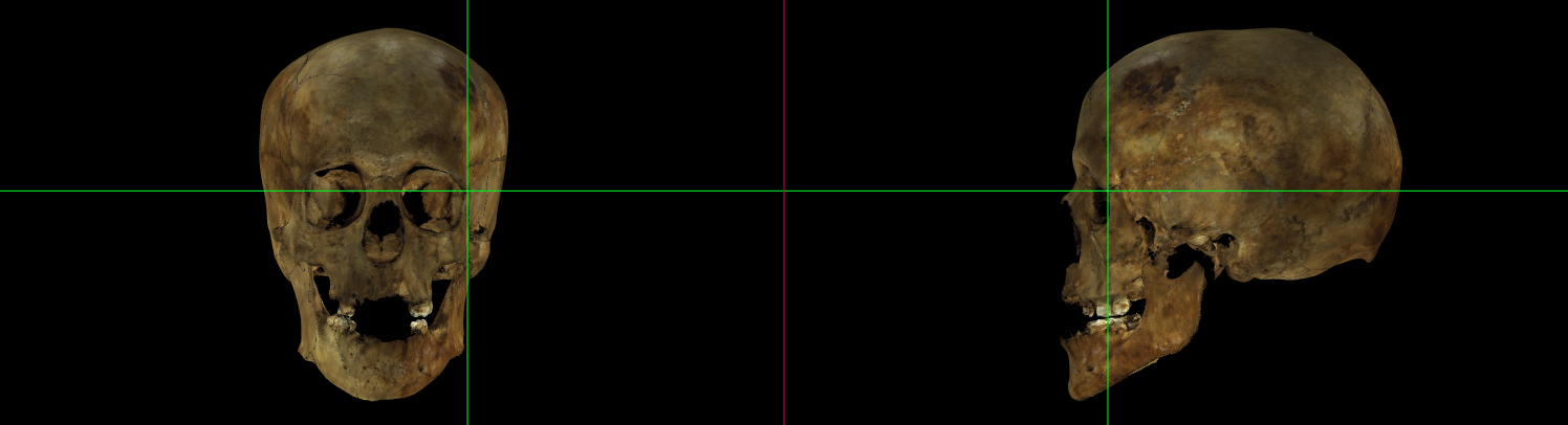 Fig. 20. Frontomalare anterior (left) on a skull 3D model in Norma Frontalis and Norma Lateralis.
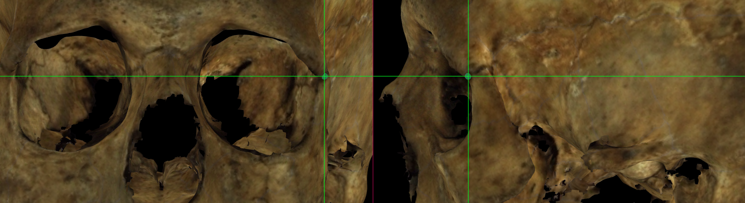 Fig. 21. Magnified image showing Frontomalare anterior (left) on a skull 3D model in Norma Frontalis and Norma Lateralis.
Observations
-
It is strictly the most anteriorly projecting point and is used for measurements relating to such projection. The suture may be, and usually is, quite irregular in its course here. No corrective for this is offered: the point is placed on the suture wherever it may lie (Howells, 1973).
-
When the suture can’t be appreciated with definition, the general course of the suture should be estimated.
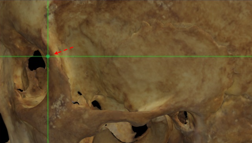 Fig. 22. Magnified image showing the estimated Frontomalare anterior (left) on a skull 3D model in Norma Lateralis with a low definition of the frontomalare suture.
Frontomalare orbitale
Abbreviation: fmo L / fmo R
Type: Frontomalare orbitale is a bilateral Type II, hard tissue craniometric landmark.
Definition
According to Caple and Stephan (2015).
Frontomalare orbitale is the point located on the orbital rim marked by the zygomaticofrontal suture.
Procedure
Frontomalare orbitale can be located on the frontal view. For a better location zoom in the area of the corresponding orbit. Use the horizontal auxiliary line as a reference over the zygomaticofrontal suture and the vertical line as a reference over the orbital rim. Follow the same procedure for the contralateral point.
 Fig. 23. Frontomalare orbitale (left) on a skull 3D model in Norma Frontalis and Norma Lateralis.
 Fig. 24. Magnified image showing Frontomalare orbitale (left) on a skull 3D model in Norma Frontalis and Norma Lateralis.
Observations
-
Do not confuse with frontomalare anterior, this is located in the most anterior part of the suture while frontomalare orbitale is located on the orbital rim at the level of the suture.
-
When the suture can’t be appreciated with definition, the general course of the suture should be estimated.
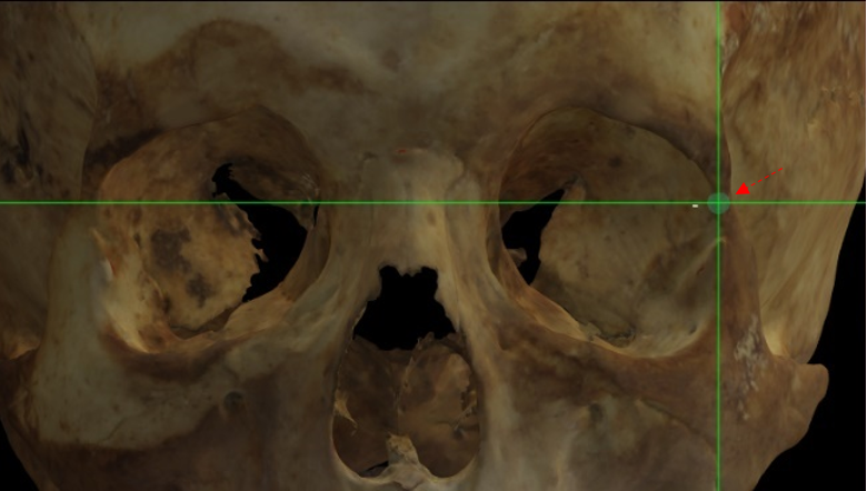 Fig. 25. Magnified image showing the estimated Frontomalare orbitale (left) on a skull 3D model in Norma Frontalis and Norma Lateralis with a low definition of the suture.
Frontomalare temporale
Abbreviation: fmt L / fmt R
Type: Frontomalare temporale is a bilateral Type III, hard tissue craniometric landmark.
Definition
According to Caple and Stephan (2015).
Frontomalare temporale is located at the most lateral part of the zygomaticofrontal suture.
Procedure
Frontomalare temporale can be located in lateral view. For a better location zoom in the area of the corresponding orbit. Use the horizontal auxiliary line as a reference over the zygomaticofrontal suture and the vertical line as a reference of the most lateral part of the suture. Follow the same procedure for the contralateral point.
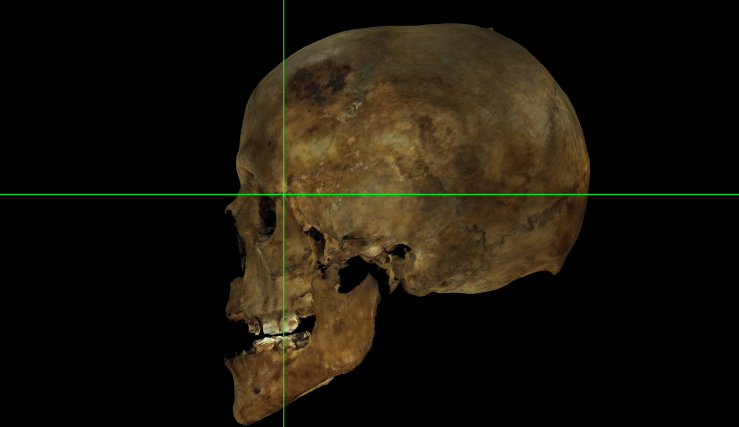 Fig. 26. Frontomalare temporale (left) on a skull 3D model in Norma Lateralis.
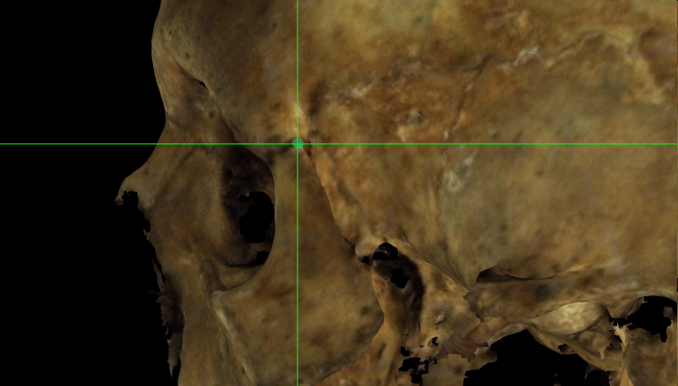 Fig. 27. Magnified image showing Frontomalare temporale (left) on a skull 3D model in Norma Lateralis.
Observations
When the suture can’t be appreciated with definition, the general course of the suture should be estimated.
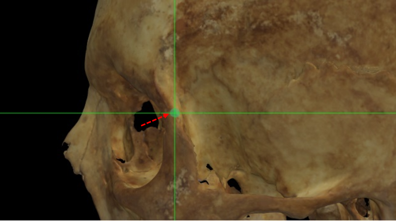 Fig. 28. Magnified image showing the estimated Frontomalare temporale (left) on a skull 3D model with low definition of the suture in Norma Lateralis.
Frontotemporale
Abbreviation: ft L / ft Z
Type: Frontotemporale is a bilateral Type II, hard tissue craniometric landmark.
Definition
According to Caple and Stephan (2015).
Frontotemporale is the most anterior and medial point of the inferior temporal line, on the zygomatic process of the frontal bone.
Procedure
Frontotemporale can be located on the frontal view and adjusted in the lateral view. For a better location zoom in the area of the temporal line. In frontal view, use the auxiliary vertical line as a reference of the most anterior area of the inferior temporal line. The auxiliary horizontal line can serve as a reference of the medial plane on the inferior temporal line. Adjust the position of the point in lateral view over the temporal line. Follow the same procedure for the contralateral point.
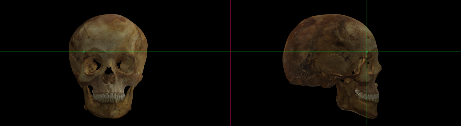 Fig. 29. Frontotemporale (right) on a skull 3D model in Norma Frontalis and Norma Lateralis.
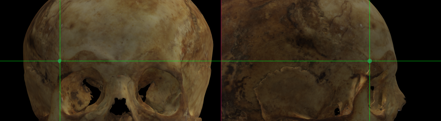 Fig. 30. Magnified image showing Frontotemporale (right) on a skull 3D model in Norma Frontalis and Norma Lateralis.
Observations
The right and left frontotemporale form the endpoints of the minimum frontal breadth measurements (Martin and Knussmann, 1988).
Gonion
Abbreviation: go L / go R
Type: Gonion is a bilateral Type II, hard tissue craniometric landmark.
Definition
According to Caple and Stephan (2015).
Gonion is the point on the rounded margin of the angle of the mandible, bisecting two lines one following vertical margin of ramus and one following horizontal margin of corpus of mandible.
Procedure
To determine the location of gonion we can use the lateral view. For a better location zoom in the area of the mandible. Use the vertical auxiliary line as a reference of the vertical line of the rammus of the mandible and place it at the rounded margin. Follow the same procedure for the contralateral point.
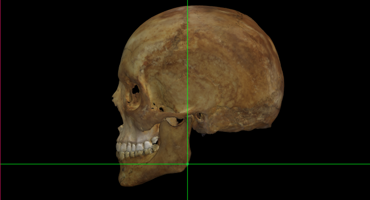 Fig. 31. Gonion (left) on a skull 3D model in Norma Lateralis.
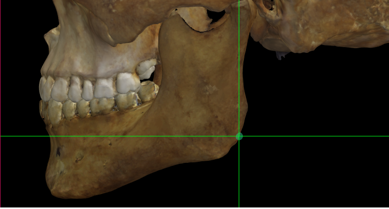 Fig. 32. Magnified image showing Gonion (left) on a skull 3D model in Norma Lateralis.
Observations
If the mandibular angle is not pronounced, is positioned at the highest point of the curvature where the posterior margin of the ramus and the inferior border of the body meet (Martin and Knussmann, 1988).
Mastoidale
Abbreviation: ms L / ms R
Type: Mastoidale is a bilateral Type II, hard tissue craniometric landmark.
Definition
According to Caple and Stephan (2015).
Mastoidale is the most posterior point of the mastoid notch.
Procedure
Locate mastoidale in lateral view and adjust in occipital view. For a better location zoom in the area of the mastoid notch. In lateral view, use the horizontal auxiliary line to determine the tip of the mastoid notch. If it necessary, adjust in occipital view. Follow the same procedure for the contralateral point.
 Fig. 33. Mastoidale (left) on a skull 3D model in Norma Occipitalis and Norma Lateralis.
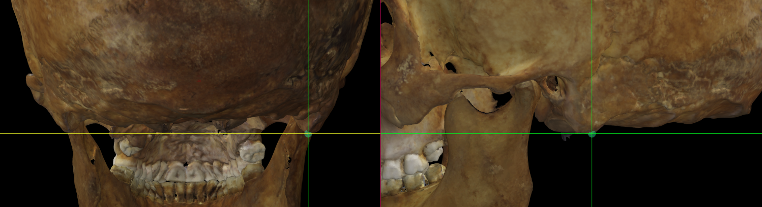 Fig. 34. Magnified image showing Mastoidale (left) on a skull 3D model in Norma Occipitalis and Norma Lateralis.
Maxillofrontale
Abbreviation: mf L / mf R
Type: Maxillofrontale is a bilateral Type I, hard tissue craniometric landmark.
Definition
According to Caple and Stephan (2015).
Maxillofrontale is located at the intersection of the anterior lacrimal crest with the frontomaxillary suture.
Procedure
Locate maxillofrontale in frontal view. For a better location zoom in the area of the nasal root. Use the vertical auxiliary line as a reference to determine the intersection of the lacrimal crest with the frontomaxillary suture. The horizontal line should be over the suture. Follow the same procedure for the contralateral point.
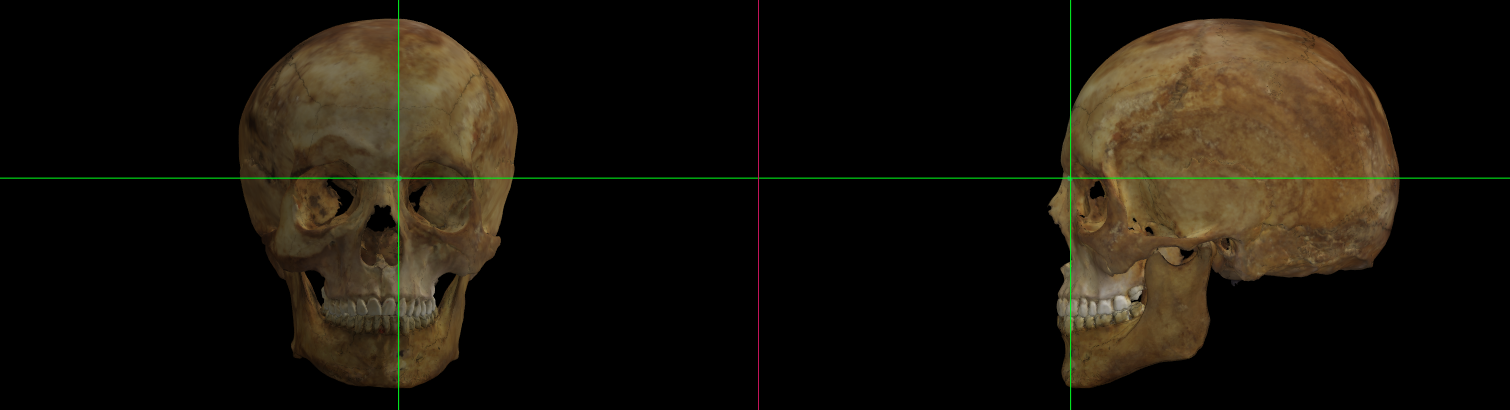 Fig. 35. Maxillofrontale (left) on a skull 3D model in Norma Frontalis and Norma Lateralis.
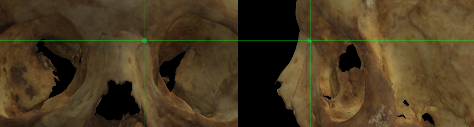 Fig. 36. Magnified image showing Maxillofrontale (left) on a skull 3D model in Norma Frontalis and Norma Lateralis.
Mid-supraorbitale
Abbreviation: mso L / mso R
Type: Mid-supraorbitale is a bilateral Type II, hard tissue craniometric landmark.
Definition
According to Caple and Stephan (2015).
Mid-supraorbitale is the point on the anterior aspect of the superior orbital rim, at the line that vertically bisects the orbit.
Procedure
To locate menton mid-supraorbitale use the frontal view. For a better location zoom in the corresponding orbit. Use the vertical auxiliary line as a reference plane to bisect the orbit vertically in two equal halves. The horizontal line must be in contact with the anterior border of the superior orbital rim. Follow the same procedure for the contralateral point.
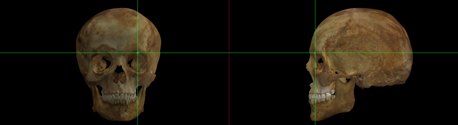 Fig. 37. Mid-supraorbitale (left) on a skull 3D model in Norma Frontalis and Norma Lateralis.
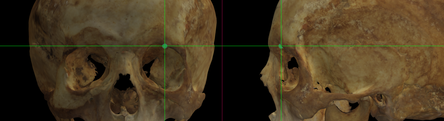 Fig. 38. Magnified image showing Mid-supraorbitale (left) on a skull 3D model in Norma Frontalis and Norma Lateralis.
Observations
The inaccurate 3D skull acquisition and/or the specific features not properly scanned at the orbital region, such as the superior orbital rim border can difficult or make impossible the location of mid-supraorbitale.
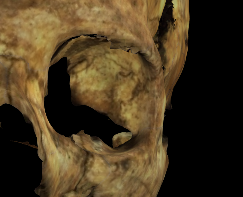 Fig. 39. Magnified image showing a bad scanned (with noise) left orbit on a skull 3D model in Norma Frontalis.
Orbitale
Abbreviation: or L / or R
Type: Orbitale is a bilateral Type II, hard tissue craniometric landmark.
Definition
According to Caple and Stephan (2015).
Orbitale is the most inferior point on the inferior orbital rim. Usually falls along the lateral half of the orbital margin.
Procedure
The left orbital must be placed in the free camera mode to compute the Frankfurt pane. For this reason, the auxiliary lines are not available. The skull must be oriented manually in frontal or lateral view in order to determine the most inferior point of the left inferior orbital rim. Once the Frankfurt plane is computed, we can adjust the position using the horizontal auxiliary line to determine the most inferior area of the orbital rim.
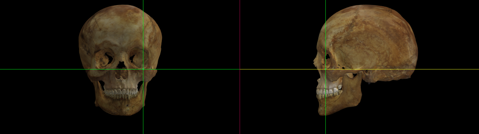 Fig. 40. Orbitale (left) on a skull 3D model in Norma Frontalis and Norma Lateralis.
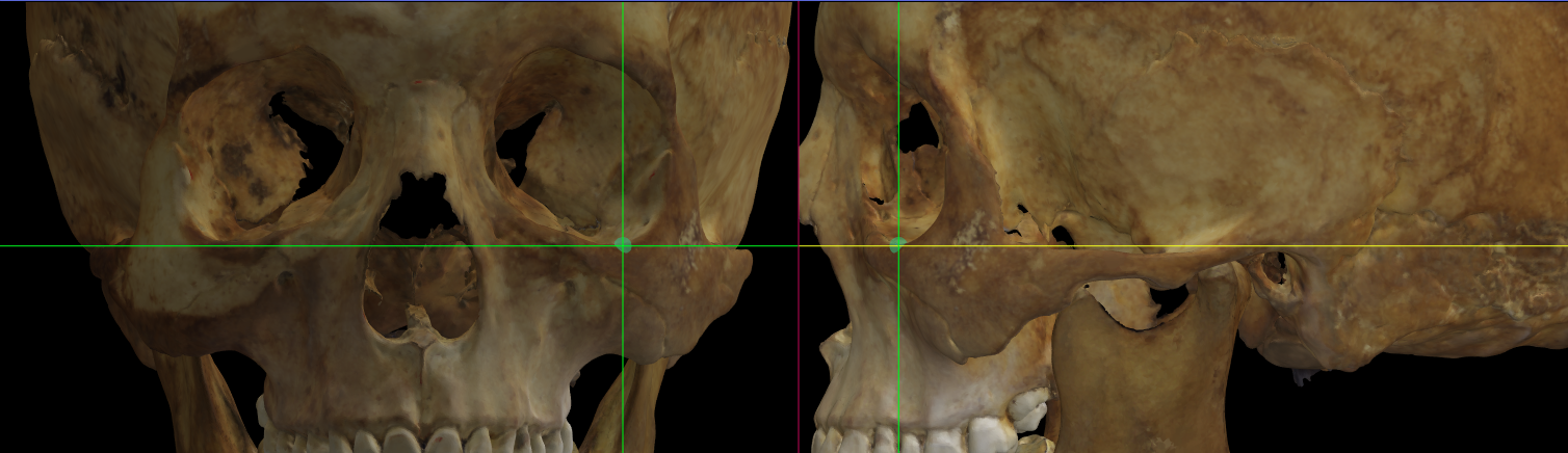 Fig. 41. Magnified image showing Orbitale (left) on a skull 3D model in Norma Frontalis and Norma Lateralis.
Porion
Abbreviation: po L / po R
Type: Porion is a bilateral Type II, hard tissue craniometric landmark.
Definition
According to Caple and Stephan (2015).
Porion is the most superior point on the upper margin of the external auditory meatus.
Procedure
The left and right porion must be placed in the free camera mode to compute the Frankfurt pane. For this reason, the auxiliary lines are not available. The skull must be oriented manually in order to determine the most superior point of the upper margin of the external auditory meatus. Once the Frankfurt plane is computed, we can adjust the position using the horizontal auxiliary line to determine the most superior area of the external auditory meatus.
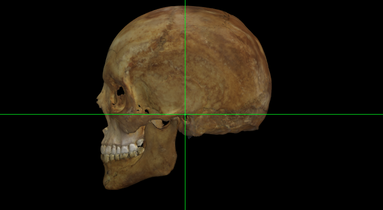 Fig. 42. Porion (left) on a skull 3D model in Norma Lateralis.
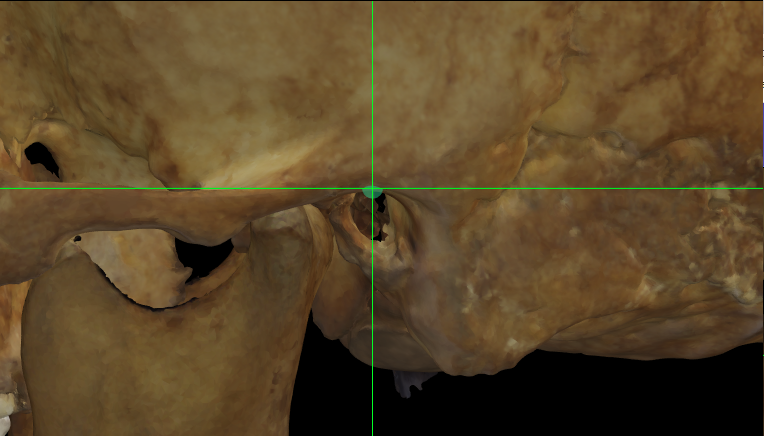 Fig. 43. Magnified image showing Porion (left) on a skull 3D model in Norma Lateralis.
Zygion
Abbreviation: zy L / zy R
Type: Zygion is a bilateral Type III, hard tissue craniometric landmark.
Definition
According to Caple and Stephan (2015).
Zygion is the most lateral point on the zygomatic arch.
Procedure
Locate zygion in frontal view. For a better location zoom in the area of the zygomatic arch. The vertical auxiliary line must be in contact with the most lateral border of the zygomatic arch. Follow the same procedure for the contralateral point.
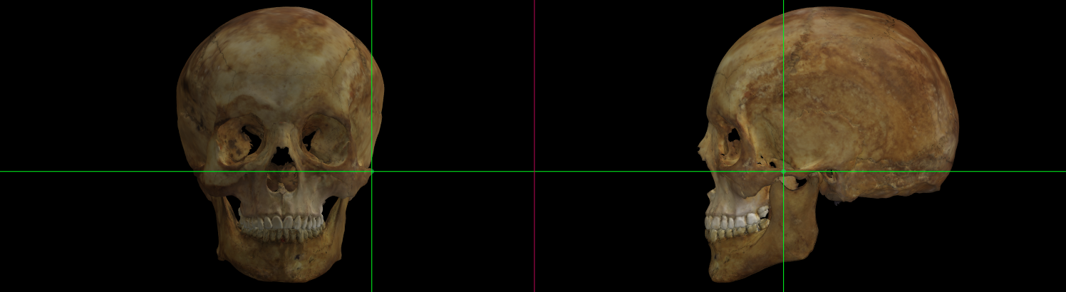 Fig. 44. Zygion (left) on a skull 3D model in Norma Frontalis and Norma Lateralis.
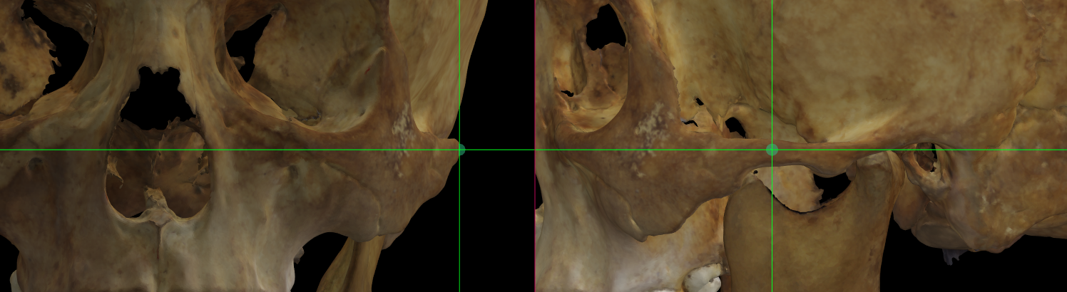 Fig. 45. Magnified image showing Zygion (left) on a skull 3D model in Norma Frontalis and Norma Lateralis.
Observations
The position of zygion is defined from the measurement of bizygomatic breadth (Martin and Knussmann, 1988).
Zygomaxillare
Abbreviation: zm L / zm R
Type: Zygomaxillare is a bilateral Type III, hard tissue craniometric landmark.
Definition
According to Caple and Stephan (2015).
Zygomaxillare is the most prominent point located at around the lower end of the zygomaxillary suture.
Procedure
Use the frontal view to locate zygomaxillare. For a better location zoom in the area of the zygomaxillary suture. As a reference the vertical auxiliary line must be located over the zygomaxillary suture and the horizontal auxiliary line at the most prominent border around the suture. Follow the same procedure for the contralateral point.
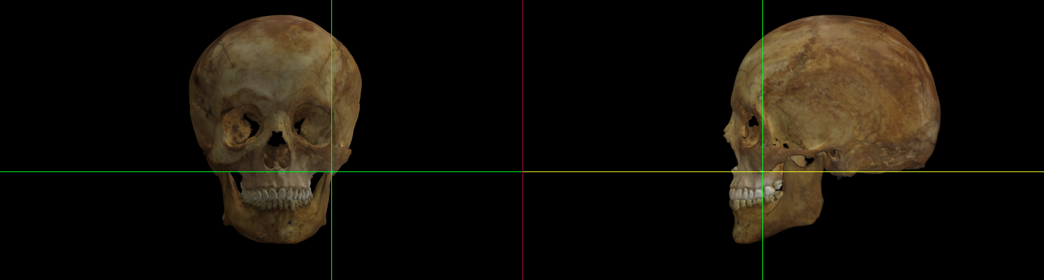 Fig. 46. Zygomaxillare (left) on a skull 3D model in Norma Frontalis and Norma Lateralis.
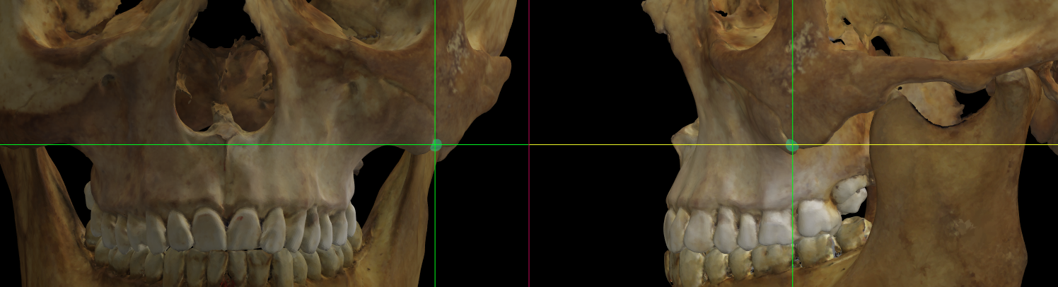 Fig. 47. Magnified image showing Zygomaxillare (left) on a skull 3D model in Norma Frontalis and Norma Lateralis.
Observations
Avoid marking zygomaxillare when the zygomaxillary suture cannot be seen with definition in the 3D model.
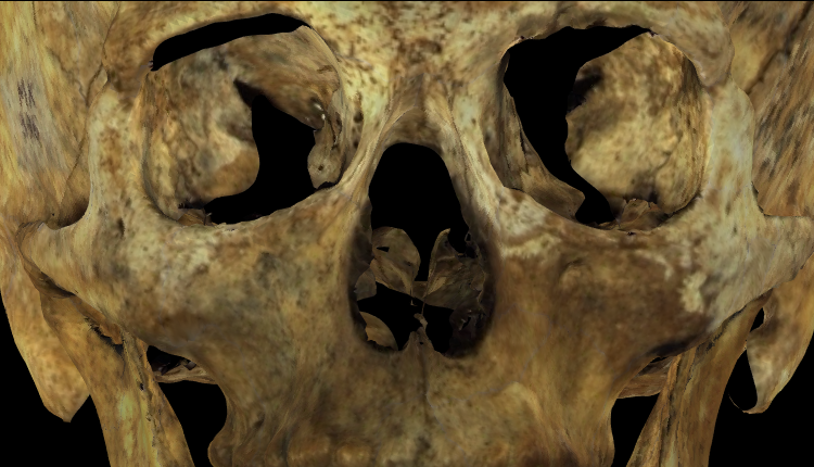 Fig. 48. Magnified image showing a skull 3D model with low definition of the zygomaxillary sutures in Norma Frontalis.
Zygoorbitale
Abbreviation: zo L / zo R
Type: Zygoorbitale is a bilateral Type II, hard tissue craniometric landmark.
Definition
According to Caple and Stephan (2015).
Zygoorbitale is the point of intersection between zygomaxillary suture and orbit border.
Procedure
Use the frontal view to locate zygoorbitale. For a better location zoom in the area of the zygomaxillary suture at the level of the corresponding orbit. As a reference the vertical auxiliary line must be located over the zygomaxillary suture and the horizontal auxiliary line at the border of the orbit. Follow the same procedure for the contralateral point.
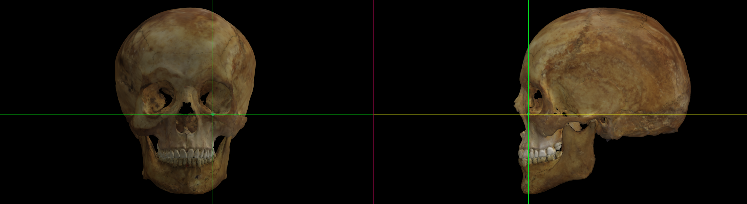 Fig. 49. Zygoorbitale (left) on a skull 3D model in Norma Frontalis and Norma Lateralis.
 Fig. 50. Magnified image showing Zygoorbitale (left) on a skull 3D model in Norma Frontalis and Norma Lateralis.
Observations
-
Since the orbital border is usually softly rounded here, the point should be found midway between the facial and orbital surfaces (Howells, 1973).
-
Avoid marking zygomaxillare when the zygomaxillary suture cannot be seen with definition in the 3D model.
 Fig. 51. Magnified image showing the maxillar bone on a skull 3D model with low definition of the zygomaxillary sutures in Norma Frontalis.