Medial Craneometric Landmarks
Basion
Abbreviation: ba
Type: Basion is a unilateral Type II, hard tissue craniometric landmark.
Definition
According to Caple and Stephan (2015).
Basion encompasses a small region, on the median plane at the anterior extent of the foramen magnum. Its position as a landmark varies slightly depending on the measurement being taken. It can be the most posterior aspect of the foramen magnum´s anterior rim or the most inferior median point on the foramen magnum´s anterior rim.
Procedure
Use the flip button to change the Norma Verticalis view for the Norma Basalis view. Basion can be located on the bottom view. For a better location zoom in the area of the foramen magnum. The vertical auxiliary line will serve as a reference of the medial plane. To determine the position of basion the horizontal auxiliary line must be in contact with the anterior border of the foramen magnum in the medial plane.
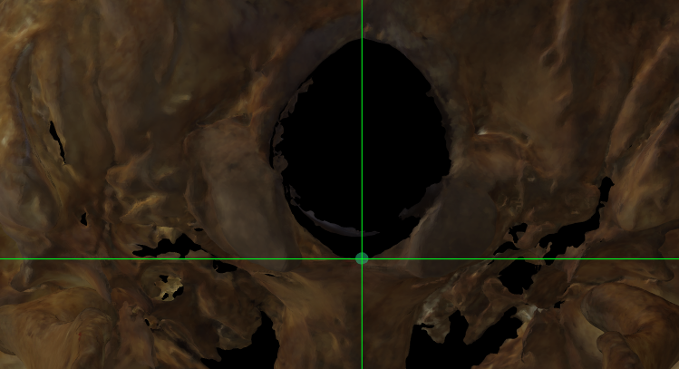 Fig. 1. Magnified image of Basion on a skull 3D model in Norma Basalis.
Observations
-
In rare cases the determination of the position of basion may be made difficult by a thickening of the anterior margin (Howells, 1973).
-
The inaccurate 3D skull acquisition and/or the specific features not properly scanned at the foramen magnum region can difficult or make impossible the location of basion.
 Fig. 2. Magnified image of the foramen magnum region on a skull 3D model in Norma Basalis where the foramen rim presents noise (inaccurate scan).
Bregma
Abbreviation: b
Type: Bregma is a unilateral Type I, hard tissue craniometric landmark.
Definition
According to Caple and Stephan (2015).
Bregma is located where the sagittal and coronal sutures meet. Impossible to determine in juvenile skulls with anterior fontanelle, or adults with complete suture obliteration.
Procedure
Bregma can be located on the top view. For a better location zoom in the area of the intersection of the coronal and sagittal sutures. Use the auxiliary lines as reference to determine the intersection of both sutures.
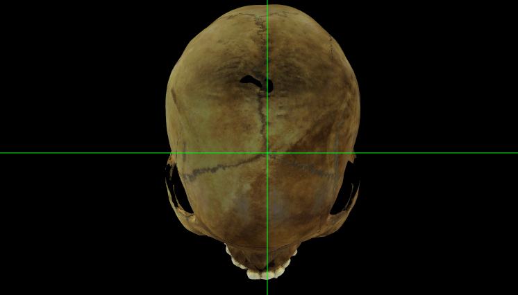 Fig. 3. Bregma on a skull 3D model in Norma Verticalis.
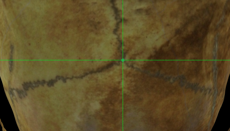 Fig. 4. Magnified image of Bregma on a skull 3D model in Norma Verticalis.
Observations
In cases where the most anterior segment of the sagittal suture deflects to one side, the point of the junction of the two sutures must be projected. In cases of asymmetry of the coronal suture, the general course of the suture should be determined, and the bregma established on this. The point should mark the limits of the frontal and parietal segments of the vault generally, not minor sutural variations (Howells, 1973).
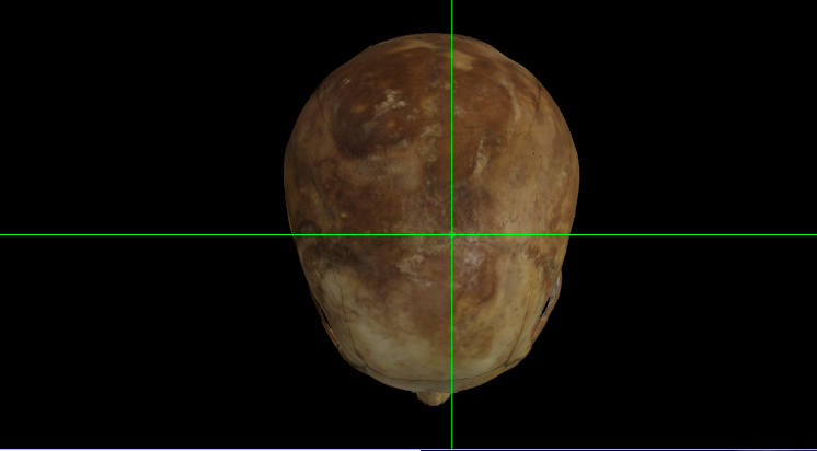 Fig. 5. Bregma on a skull 3D model in Norma Verticalis. The most anterior segment of the sagittal suture deflects to the left side.
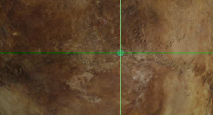 Fig. 6. Magnified image of Bregma on a skull 3D model in Norma Verticalis.
Glabella
Abbreviation: g
Type: Glabella is a unilateral Type II, hard tissue craniometric landmark.
Definition
According to Caple and Stephan (2015).
Glabella is the most projecting anterior median point on lower edge of the frontal bone, on the brow ridge, between the superciliary arches and above the nasal root. In adults, glabella usually represents the most anterior point of the frontal bone.
Procedure
To determine the location of glabella we can use the lateral and frontal view. For a better location zoom in the area of the brow ridge. In lateral view the vertical auxiliary line must be in contact with the edge of the most prominent area of the brow ridge. Later, we will make an adjustment in frontal view placing the vertical line in the mid-sagittal plane. As a reference the horizontal line must be located over the superciliary arches.
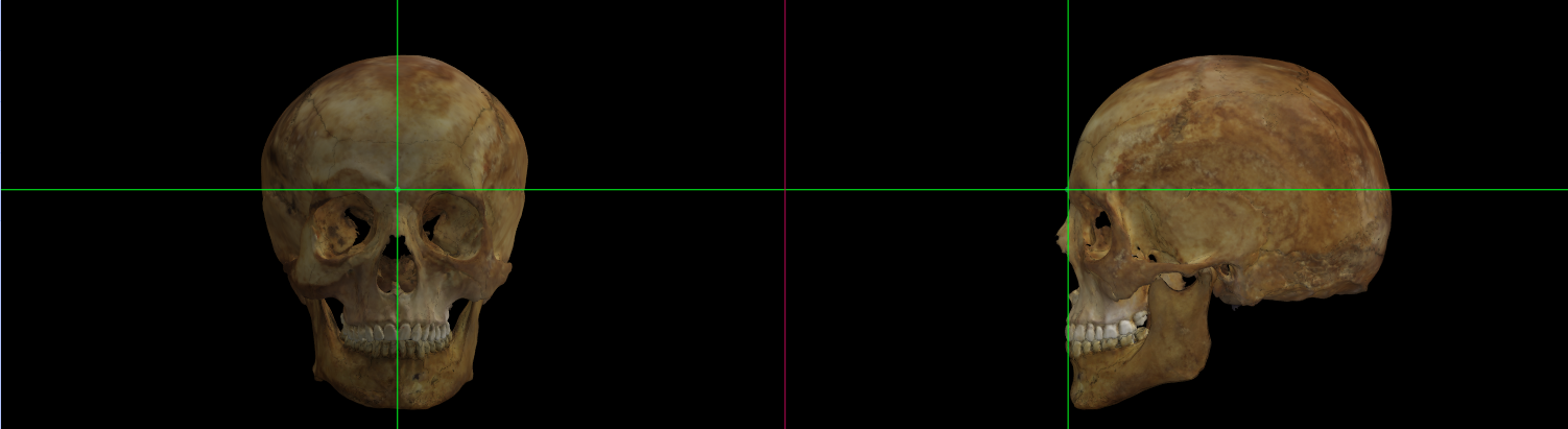 Fig. 7. Glabella on a skull 3D model in Norma Frontalis and Norma Lateralis.
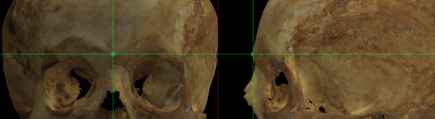 Fig. 8. Magnified image showing Glabella on a skull 3D model in Norma Frontalis and Norma Lateralis.
Observations
The point of glabella is depressed between the confining bony ridges and is often delineated superiorly by a shallow gutter or a transversaly running indentation on the surface of the frontal bone (Martin and Knussmann, 1988).
Gnathion
Abbreviation: gn
Type: Gnathion is a unilateral Type III, hard tissue craniometric landmark.
Definition
According to Caple and Stephan (2015).
Gnathion is the median point halfway between pogonion and menton.
Procedure
To determine the location of gnathion we can use the frontal view. For a better location zoom in the area of the inferior margin of the mandible. As a reference the vertical auxiliary line must be placed in the mid-saggital plane and the horizontal line near to the inferior margin of the mandible. We recommend placing first pogonion and menton as a reference landmark to locate gnathion.
 Fig. 9. Gnathion on a skull 3D model in Norma Frontalis and Norma Lateralis.
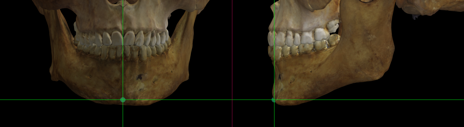 Fig. 10. Magnified image showing Gnathion on a skull 3D model in Norma Frontalis and Norma Lateralis.
Observations
We recommend placing first pogonion and menton as a reference to locate gnathion.
Incision
Abbreviation: inc
Type: Incision is a unilateral Type II, hard tissue craniometric landmark.
Definition
According to Caple and Stephan (2015).
Incision is the the point at the occlusal surface where the upper central incisors meet.
Procedure
Incision must be located in frontal view. For a better location zoom in the area of the upper central incisors. Use the vertical auxiliary line as a reference between the incisors and the horizontal one as a reference of the occlusal surface.
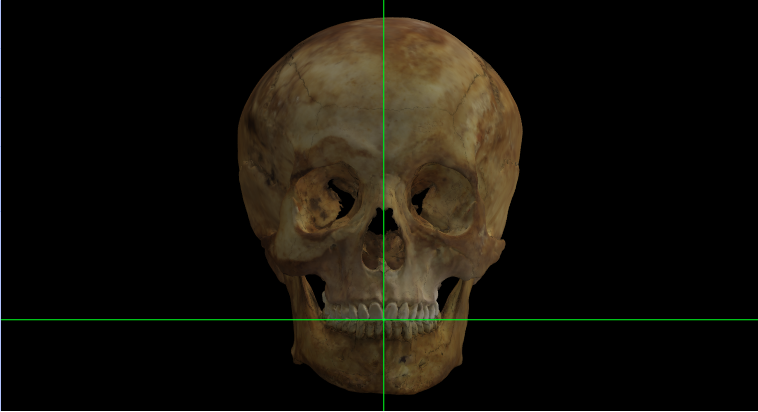 Fig. 11. Incision on a skull 3D model in Norma Frontalis.
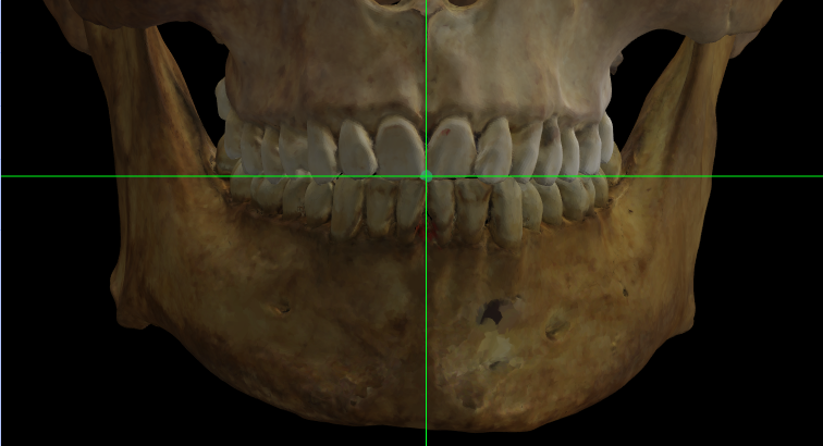 Fig. 12. Magnified image showing Incision on a skull 3D model in Norma Frontalis.
Observations
Incision cannot be marked in edentulous individuals or with the absence of the two or one of the upper central incisors.
 Fig. 13. Magnified image showing the maxilla and the mandible of an edentulous individual in Norma Frontalis.
Infradentale
Abbreviation: id
Type: Infradentale is a unilateral Type II, hard tissue craniometric landmark.
Definition
According to Caple and Stephan (2015).
Infradentale is the median point at the superior tip of the septum between the mandibular central incisors.
Procedure
To determine the location of infradentale use the frontal view. For a better location zoom in the area of the mandible. Use the vertical auxiliary line as a reference of the mid-sagittal plane between the lower central incisors. As a reference, the horizontal auxiliary line must be located on the anterior margin of the alveolar process.
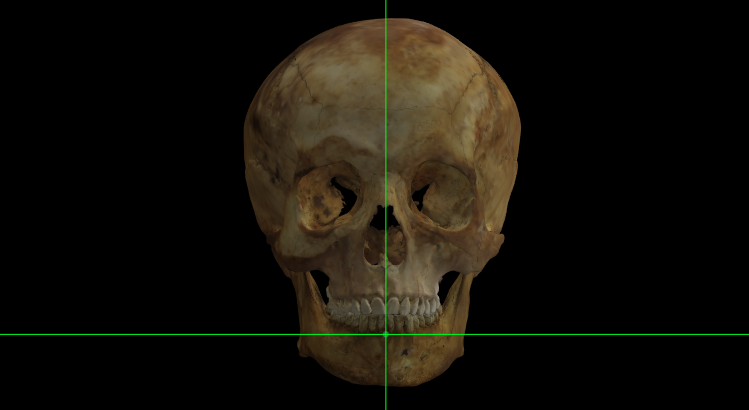 Fig. 14. Infradentale on a skull 3D model in Norma Frontalis.
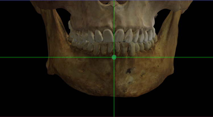 Fig. 15. Magnified image showing Infradentale on a skull 3D model in Norma Frontalis.
Observations
Avoid marking infradentale in edentulous individuals or with the absence of the inferior central incisors.
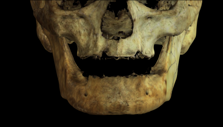 Fig. 16. Magnified image showing the maxilla and the mandible of an edentulous individual in Norma Frontalis.
Inion
Abbreviation: i
Type: Inion is a unilateral Type II, hard tissue craniometric landmark.
Definition
According to Caple and Stephan (2015).
Inion is the median point between the apices of the superior nuchal lines at the base of the external occipital protuberance.
Procedure
To locate inion use the lateral view and adjust the point in the occipital view. For a better location zoom in the area of the occipital bone. In lateral view use the vertical auxiliary line to determine the border of the occipital protuberance. The horizontal should be located on the base of the protuberance (but not in contact with the end). Then, adjust in occipital view to the midline between the apices of the nuchal lines.
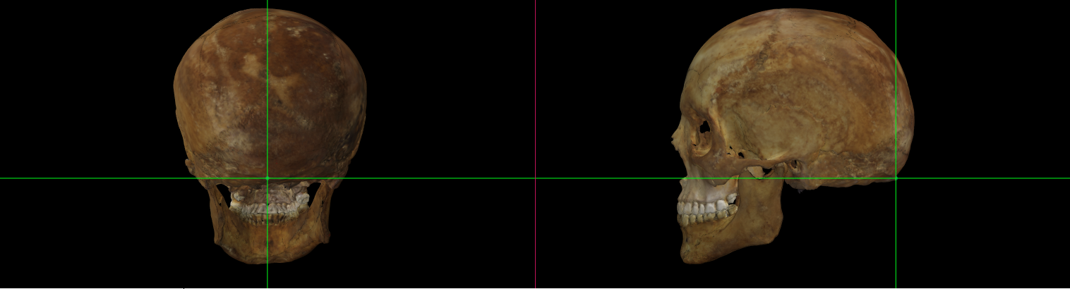 Fig. 17. Inion on a skull 3D model in Norma Occipitalis and Norma Lateralis.
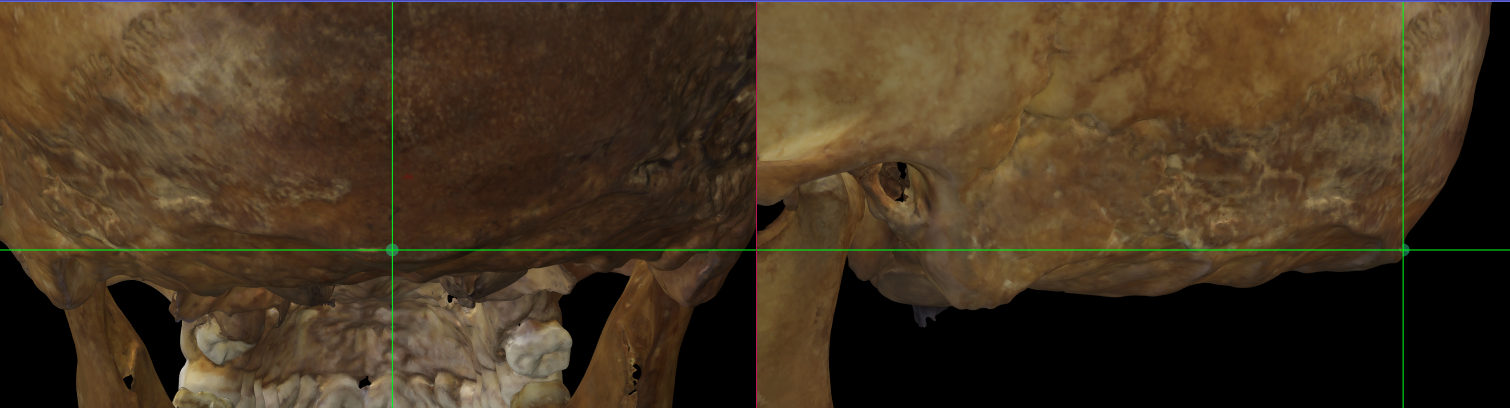 Fig. 18. Magnified image showing Inion on a skull 3D model in Norma Occipitalis and Norma Lateralis.
Observations
Inion is at the base but not at the tip of the occipital protuberance.
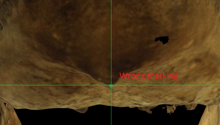 Fig. 19. Magnified image showing a wrong located Inion at the tip of the occipital protuberance on a skull 3D model in Norma Occipitalis.
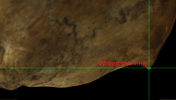 Fig. 20. Magnified image showing a wrong located Inion at the tip of the occipital protuberance on a skull 3D model in Norma Lateralis.
Lamda
Abbreviation: l
Type: Lamda is a unilateral Type I, hard tissue craniometric landmark.
Definition
According to Caple and Stephan (2015).
Lamda is the point at which the two legs of the lamboid suture and sagital suture meet ().
Procedure
Locate lamda in the occipital view. For a better location zoom in the area of the lamboid and sagittal sutures. As a reference the horizontal auxiliary line must be placed over the intersection of the two legs of the lamboid suture and sagital suture.
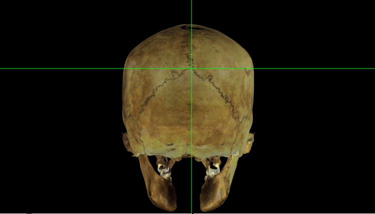 Fig. 21. Lamda on a skull 3D model in Norma Occipitalis.
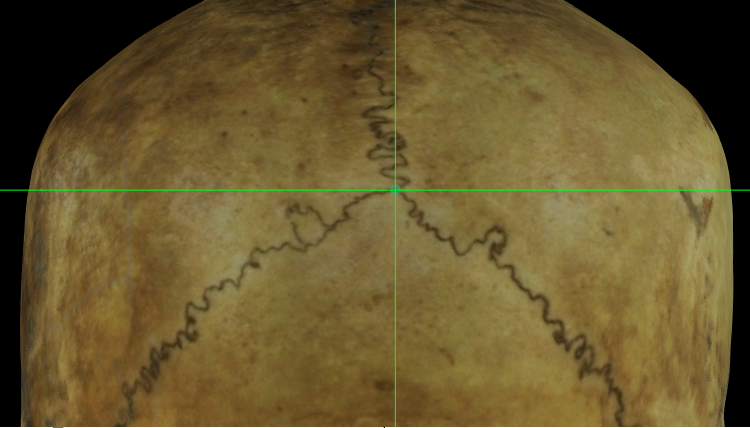 Fig. 22. Magnified image showing lamda on a skull 3D model in Norma Occipitalis.
Observations
In case of presence of Wormian bones, project from the main direction of the sutures (Howells, 1973).
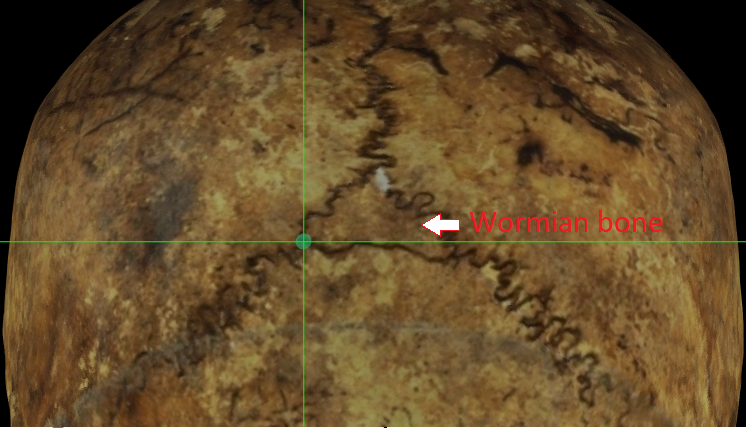 Fig. 23. Magnified image showing lamda on a skull 3D model with a Wormian bone in Norma Occipitalis.
Menton
Abbreviation: me
Type: Menton is a unilateral Type III, hard tissue craniometric landmark.
Definition
According to Caple and Stephan (2015).
Menton is the most inferior median point of the mental symphysis.
Procedure
Locate menton in the frontal view. For a better location zoom in the area of the inferior margin of the mandible. Use the vertical auxiliary line as a reference of the mid-sagittal plane. The horizontal line must be located in contact with the inferior border of the mandible.
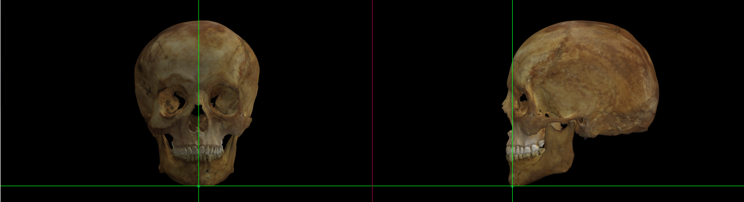 Fig. 24. Menton on a skull 3D model in Norma Frontalis and Norma Lateralis.
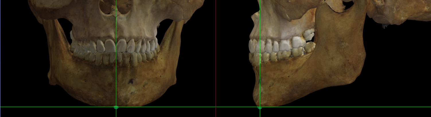 Fig. 25. Magnified image showing Menton on a skull 3D model in Norma Frontalis and Norma Lateralis.
Observations
Menton may not be the inferior point of the mandible as the chin is often clefted on the inferior margin.
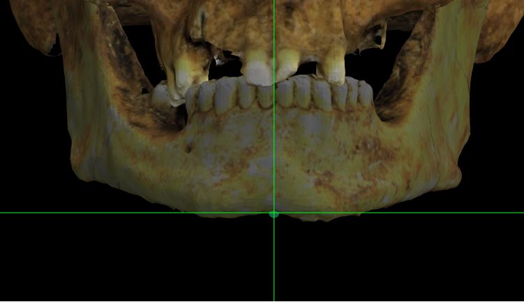 Fig. 26. Magnified image showing Menton on a skull 3D model with a clefted chin in Norma Frontalis.
Nasion
Abbreviation: n
Type: Nasion is a unilateral Type I, hard tissue craniometric landmark.
Definition
According to Caple and Stephan (2015).
Nasion is located as the intersection of the naso-frontal sutures in the median plane.
Procedure
To locate nasion use the frontal view. For a better location zoom in the nasal root area. Use the vertical auxiliary line as a reference of the mid-sagittal plane. The horizontal auxiliary line should be located at the naso-frontal suture.
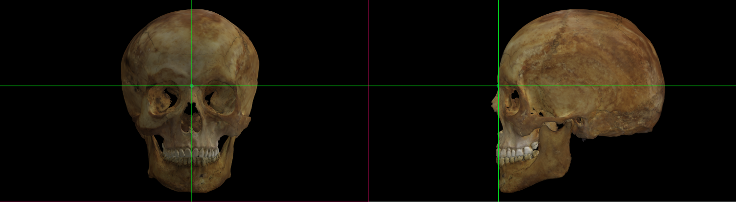 Fig. 27. Nasion on a skull 3D model in Norma Frontalis and Norma Lateralis.
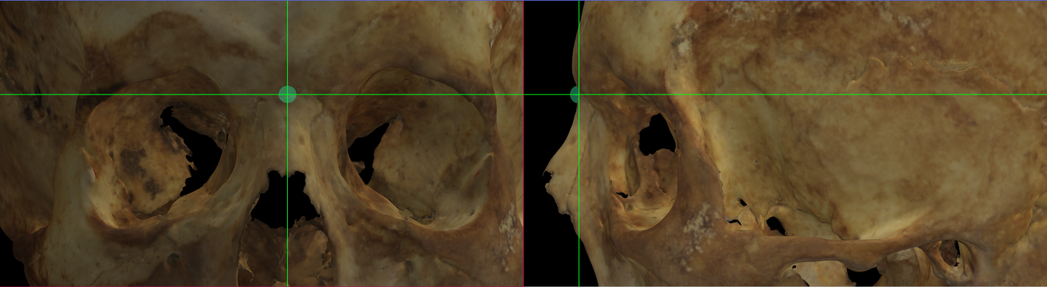 Fig. 28. Magnified image showing Nasion on a skull 3D model in Norma Frontalis and Norma Lateralis.
Observations
As a general rule, nasion is on the frontal bone at the intersection of the naso-frontal sutures in the median plane. Do not confuse with the end of the internasal suture since this may not coincide with the midplane.
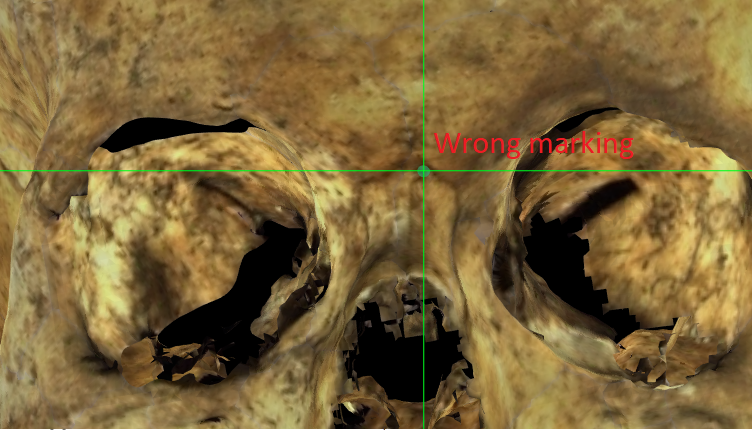 Fig. 29. Magnified image showing a wrong located Nasion on a skull 3D model in Norma Frontalis.
Ophistion
Abbreviation: o
Type: Ophistion is a unilateral Type II, hard tissue craniometric landmark.
Definition
According to Caple and Stephan (2015).
Ophistion is the median point on the anterior side of the foramen magnum´s posterior rim.
Procedure
Locate opisthion in bottom view. For a better location zoom in the area of the foramen magnum. Use the vertical auxiliary line as a reference of the median plane over the foramen magnum and the horizontal auxiliary line must be in contact with the anterior border of the posterior margin of the foramen at the median plane.
 Fig. 30. Magnified image showing Opisthion on a skull 3D model in Norma Basalis.
Observations
The inaccurate 3D skull acquisition and/or the specific features not properly scanned at the foramen magnum region can difficult or make impossible the location of ophistion.
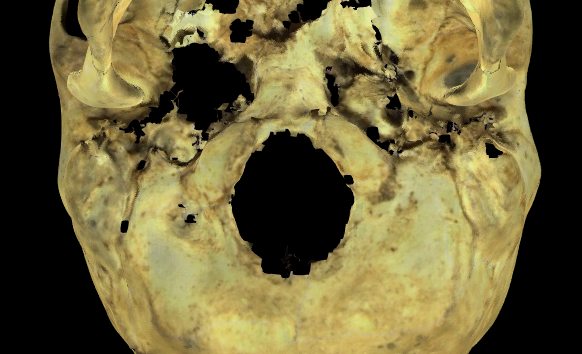 Fig. 31. Magnified image of the foramen magnum region on a skull 3D model in Norma Basalis where the foramen rim presents noise.
Ophistocranion
Abbreviation: op
Type: Ophistocranion is a unilateral Type III, hard tissue craniometric landmark.
Definition
According to Caple and Stephan (2015).
Ophistocranion is the most posterior median point of the occipital bone, instrumentally determined as the greatest chord length from glabella. Usually above the external occipital protuberance.
Procedure
To locate opisthocranion use the lateral and occipital view. For a better location zoom in the area of the occipital bone. In lateral view, use the vertical auxiliary line to determine the most posterior area of the occipital bone. Then, in occipital view, use the vertical line to adjust the point to the medial plane.
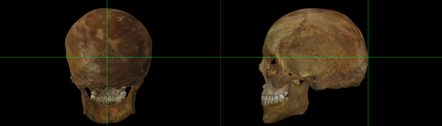 Fig. 32. Opisthocranion on a skull 3D model in Norma Occipitalis and Norma Lateralis.
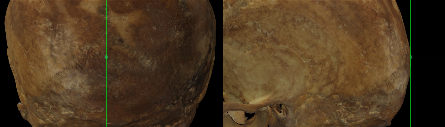 Fig. 33. Magnified image showing Opisthocranion on a skull 3D model in Norma Occipitalis and Norma Lateralis.
Observations
Ophistocranion almost always falls on the superior squama of the occipital bone, and only occasionally on the external occipital protuberance (Martin and Knussmann, 1988).
Pogonion
Abbreviation: pg
Type: Pogonion is a unilateral Type III, hard tissue craniometric landmark.
Definition
According to Caple and Stephan (2015).
Pogonion is the most anterior median point on the mental eminence of the mandible.
Procedure
To locate pogonion use the lateral and frontal views. For a better location zoom in the mental eminence area. Use the vertical auxiliary line as a reference in lateral view. This line must be located at the border of the mental eminence in the most prominent area. Posteriorly, adjust the position of pogonion in frontal view using the vertical line as a reference of the mid-sagittal plane.
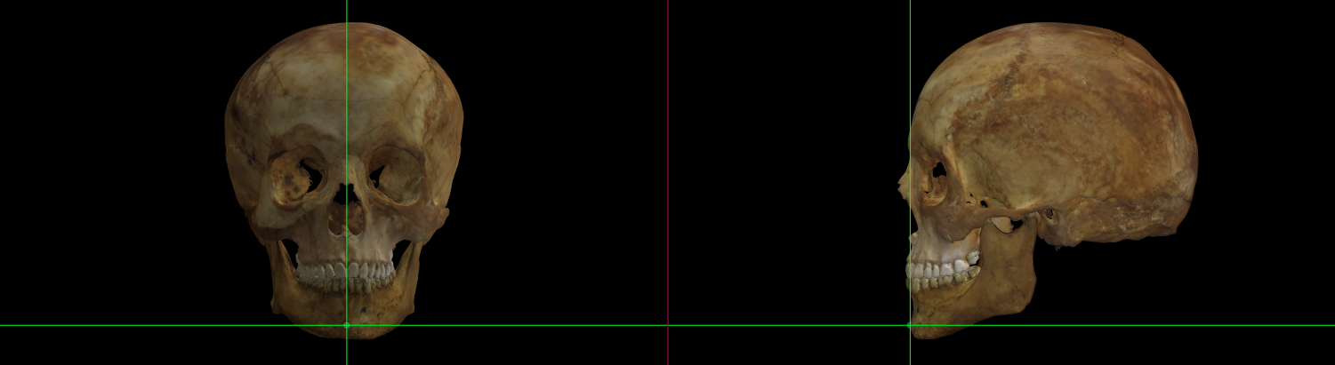 Fig. 34. Pogonion on a skull 3D model in Norma Frontalis and Norma Lateralis.
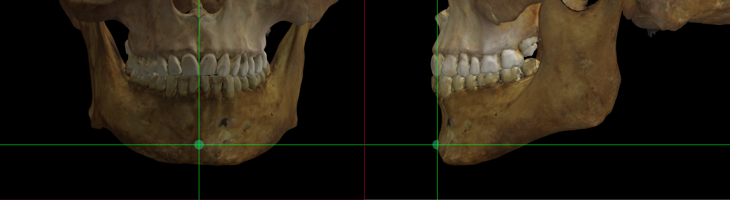 Fig. 35. Magnified image showing Pogonion on a skull 3D model in Norma Frontalis and Norma Lateralis.
Prosthion
Abbreviation: pr
Type: Prosthion is a unilateral Type II, hard tissue craniometric landmark.
Definition
According to Caple and Stephan (2015).
Prosthion is the median point between the central incisors on the anterior margin of the maxillary alveolar rim.
Procedure
To locate prosthion use the frontal view. For a better location zoom in the upper incisors area. Use the vertical auxiliary line as a reference of the mid-sagittal plane between the upper central incisors and the horizontal line should be located on the alveolar rim.
 Fig. 36. Prosthion on a skull 3D model in Norma Frontalis and Norma Lateralis.
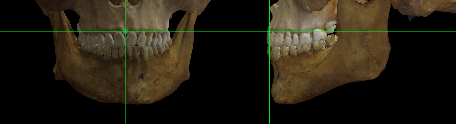 Fig. 37. Magnified image showing Prosthion on a skull 3D model in Norma Frontalis and Norma Lateralis.
Observations
Avoid marking prosthion in edentulous individuals or with the absence of the upper central incisors.
 Fig. 38. Magnified image showing the maxilla and the mandible of an edentulous individual in Norma Frontalis.
Rhinion
Abbreviation: rhi
Type: Rhinion is a unilateral Type I, hard tissue craniometric landmark.
Definition
According to Caple and Stephan (2015).
Rhinion is the most rostral (end) point on the internasal suture.
Procedure
Use the frontal view to locate rhinion. For a better location zoom in the area of the nasal bone. As a reference the vertical auxiliary line must be located over the internasal suture and the horizontal auxiliary line at the end border of the nasal bone.
 Fig. 39. Rhinion on a skull 3D model in Norma Frontalis and Norma Lateralis.
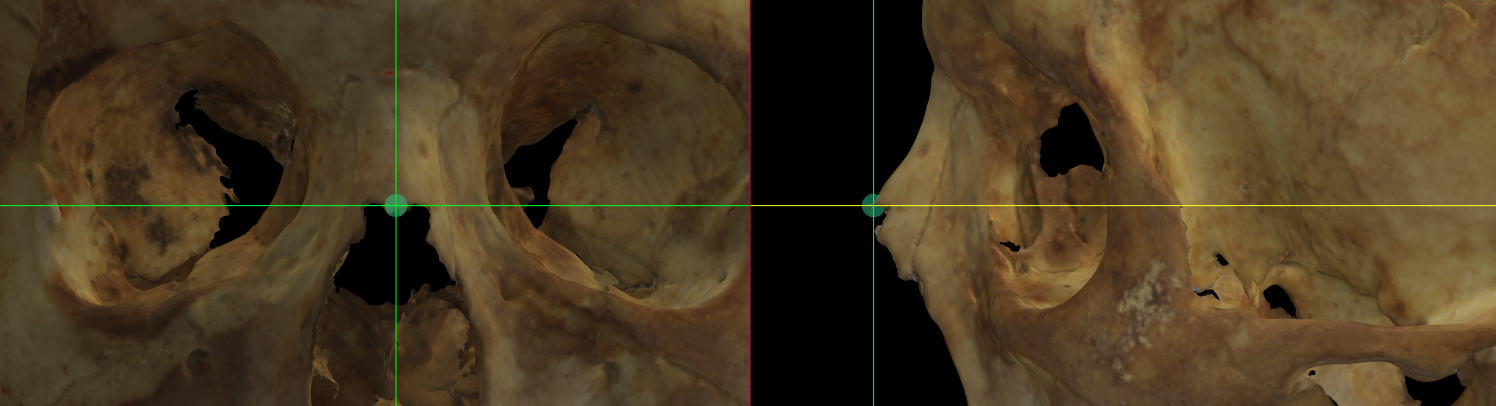 Fig. 40. Magnified image showing Rhinion on a skull 3D model in Norma Frontalis and Norma Lateralis.
Observations
-
The inaccurate 3D skull acquisition and/or the specific features not properly scanned at the nasal region, such as the nasal bone end can difficult the location of rhinion.
-
Rhinion cannot be determined accurately if the nasal bone is broken distally.
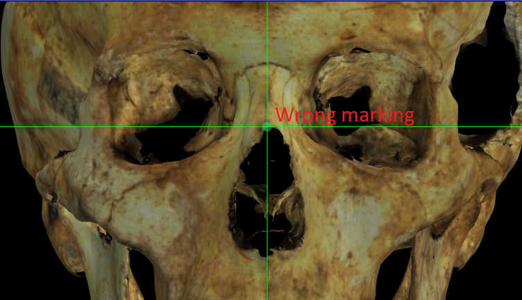 Fig. 41. Magnified image showing a wrong located Rhinion on a skull 3D model with the nasal bone broken in Norma Frontalis.
Subspinale
Abbreviation: ss
Type: Subespinale is a unilateral Type II, hard tissue craniometric landmark.
Definition
According to Caple and Stephan (2015).
Subspinale is the deepest point seen in the profile view below the anterior nasal spine.
Procedure
To locate this point, we will first use the lateral view for later adjustment in the frontal view. In the lateral view, the horizontal auxiliary line must be located below the anterior nasal spine and the vertical line in contact with the edge of the deepest area under the spine. For an adjustment in frontal view, we will use the vertical line to place the point in the mid-sagittal plane.
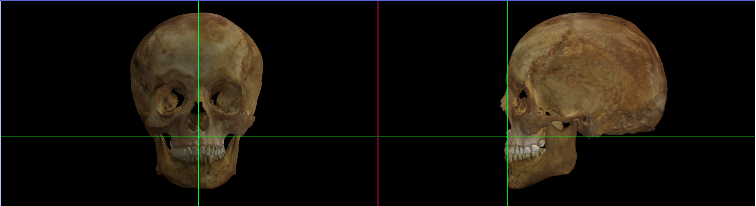 Fig. 42. Subspinale on a skull 3D model in Norma Frontalis and Norma Lateralis.
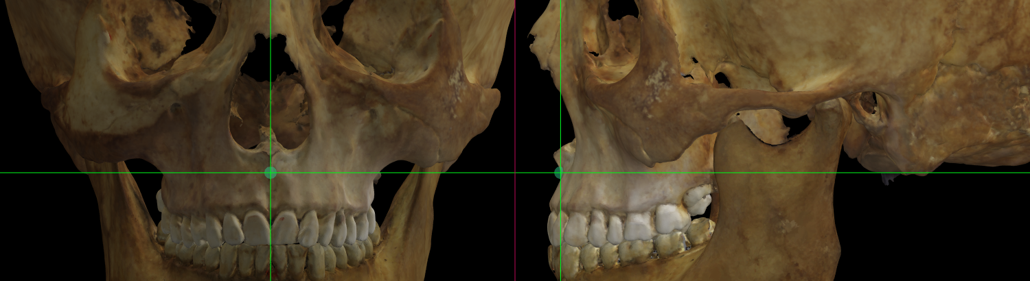 Fig. 43. Magnified image showing Subspinale on a skull 3D model in Norma Frontalis and Norma Lateralis.
Observations
If the nasal spine is small or eroded, the point is difficult to locate. It should not be placed internal to the outermost limit of the lower border of the aperture (Howells, 1975).
Supramentale
Abbreviation: sm
Type: Supramentale is a unilateral Type II, hard tissue craniometric landmark.
Definition
According to Caple and Stephan (2015).
Supramentale is the deepest median point in the groove superior to the mental eminence.
Procedure
To locate this point, we will first use the lateral view for later adjustment in the frontal view. In the lateral view, the vertical auxiliary line must be in contact with the anterior border of the deepest area of the groove over the mental eminence. The horizontal line must be placed at the midline of the groove. For an adjustment in frontal view, use the vertical line to place the point in the mid-sagittal plane.
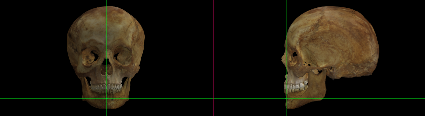 Fig. 44. Supramentale on a skull 3D model in Norma Frontalis and Norma Lateralis.
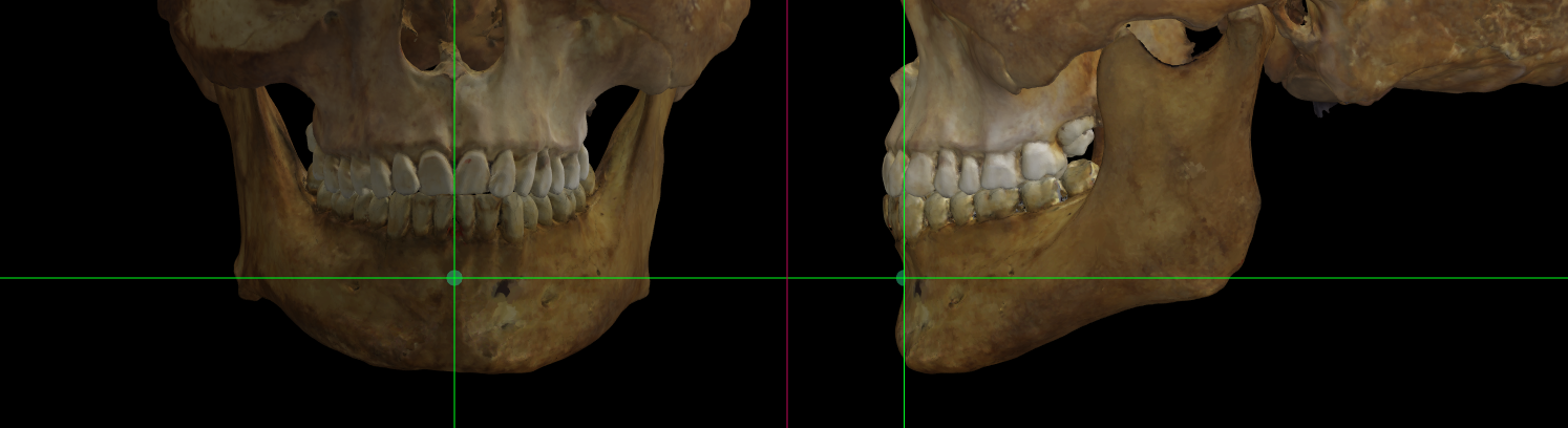 Fig. 45. Magnified image showing Supramentale on a skull 3D model in Norma Frontalis and Norma Lateralis.
Vertex
Abbreviation: v
Type: Vertex is a unilateral Type III, hard tissue craniometric landmark.
Definition
According to Caple and Stephan (2015).
Vertex is the most superior point of the skull with respect to the mid sagittal plane.
Procedure
Locate vertex in frontal view. For a better location zoom in the upper cranial contour. The vertical auxiliary line must be located in the mid-sagittal plane and the horizontal auxiliary line must be in contact with the superior border of the cranial contour.
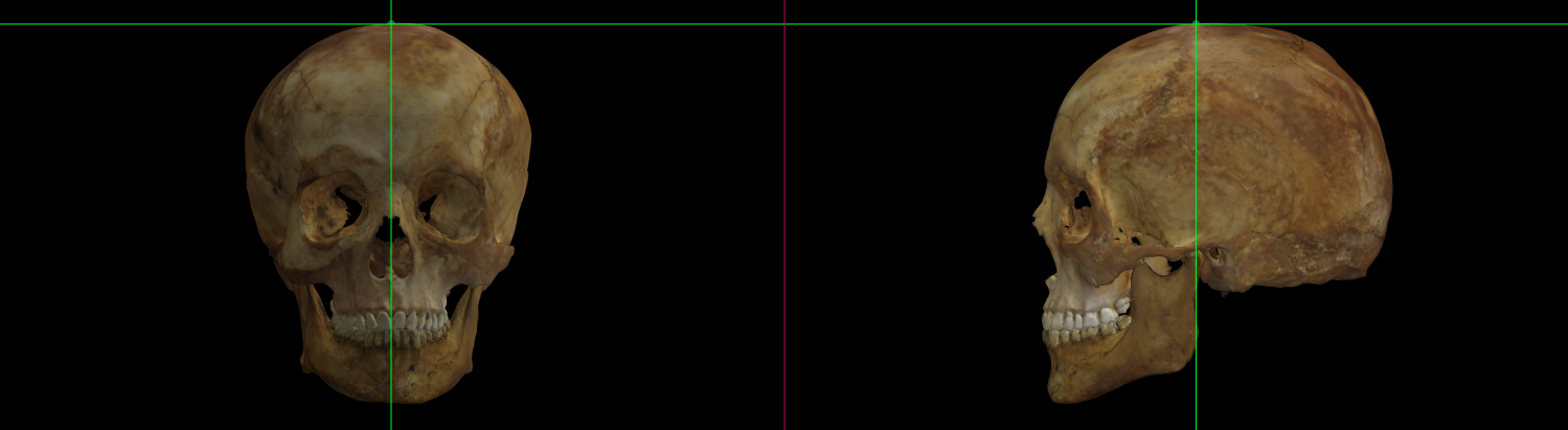 Fig. 46. Vertex on a skull 3D model in Norma Frontalis and Norma Lateralis.
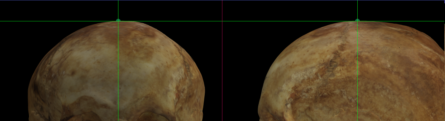 Fig. 47. Magnified image showing Vertex on a skull 3D model in Norma Frontalis and Norma Lateralis.