Skeleton·ID: Virtual Lab
The Virtual Lab is organized in five different scenes:
- Cases selector.
- 2D landmarking.
- Skull-mandible attachment.
- 3D landmarking.
- Skull-face overlay.
 Fig. 1. Skeleton·ID icons.
In this manual we will mainly focus on the “3D landmarking” scene, however, we will first explain how to load new 3D skull models in the “Case selector” scene.
Case selector
| CASE SELECTOR OPTION | ACTIONS |
|---|---|
 |
Open a case file (investigation) that contains the AM and PM cases. |
 |
Open an AM case that contains the photographs. |
 |
Open a photograph of the selected AM case. |
 |
Open a PM case that contains the skull 3D model. |
 |
Open a Skull 3D model of the selected PM case. |
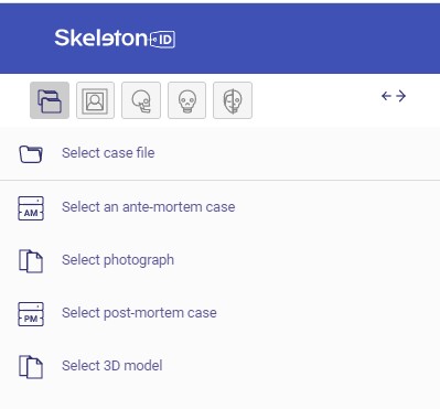 Fig. 2. Skeleton·ID case selector options.
Create a new landmark location set
- By default, after loading a 3D model, a new landmark location set will appear. To create our own set, we must click on the three doos and select “New Location set”.
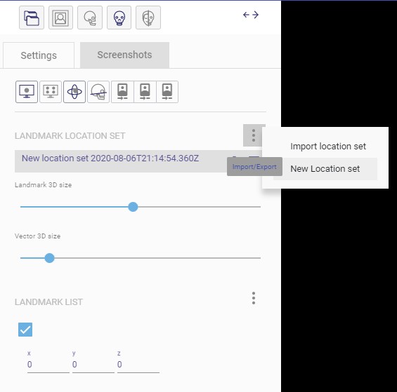 Fig. 3. New landmark locarion set creation.
- A pop-up window will appear where we must configure the name of the new location set, its description and select the landmark set to use (by default the Skeleton·ID landmark set).
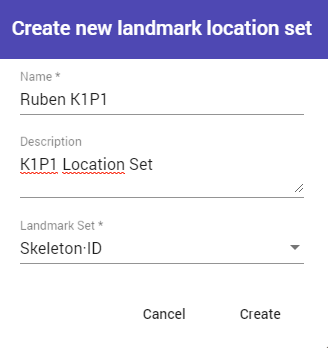 Fig. 4. Landmarks location set options.
-
This option allows us to create multiple location sets so that different users can work on the same 3D model at the same time.
-
In the same button, but selecting “Import location set”, we can import into skeleton·id and load a previously exported landmark location set.
-
The export button,
 allows to export and save locally a selected location set.
3D landmarking tools
| 3D LANDMARKING TOOLS | ACTIONS |
|---|---|
 |
Free camera view. Activated by default. Allow to rotate, translate and scale the skull freely. |
 |
Display 4 screens with the skull positioned in the Frankfurt plane. It will available once the Frankfurt plane has been established. |
 |
Display the auxiliary rotation widget. |
 |
Show the Frankfurt plane (grid). |
 |
Flip frontal, lateral and top camera in Frankfurt plane view. |
| Landmark 3D size | Modify the dot size. |
| Vector 3D size | Modify the vector size. Note that this vector is employed to represents the direction of the corresponding soft tissue landmark. |
 Fig. 5. Skeleton·ID 3D editor. At the left the 3D editor tools panel. The rotation widget and the landmark selector window are displayed.
Mouse controls
| MOUSE CONTROLS | ACTIONS |
|---|---|
| Mouse Left-Click Button | Skull rotation |
| Mouse Right-Click Button | Display landmark selector window |
| Mouse Wheel-Click Button | Skull translation |
| Mouse Wheel Button | Skull scaling (zoom) |
Procedure to compute the Frankfurt Horizontal plane
The Frankfurt Horizontal plane (FH) (Fig. 3) was adopted by anthropologists/craniologists in 1884, following discussions held at the Craniometrical Conferences in Munich (1877), Berlin (1880) and Frankfurt am Main (1882) as a consensus method to orient dry skulls in a standard upright position.
Definition
The anatomical position of the human skull based on a plane passing through the inferior margin of the left orbit and the upper margin of each ear canal or external auditory meatus.
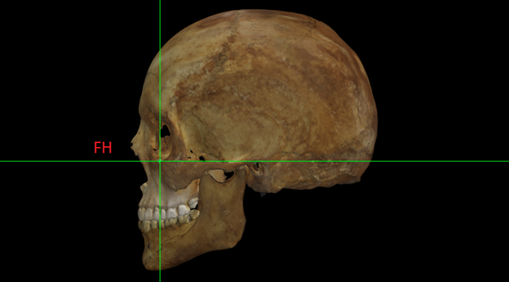 Fig. 6. Skull 3D model positioned in the Frankfurt Horizontal plane.
Procedure
In order to establish the FH plane, it will be necessary to locate and place the left and right porion and the left orbitale landmarks1 in the free camera view.
Once the previous 3 landmarks are positioned the FH plane is computed. This step is necessary to help the positioning of several landmarks.
Now, the FH button will be available, which is composed of 4 screens (Fig. 7 and 8) with different views2 of the skull:
Fig. 7. (A) Norma Frontalis; (B) Normal Lateralis (left); (C) Norma Verticalis and (D) Free camera.
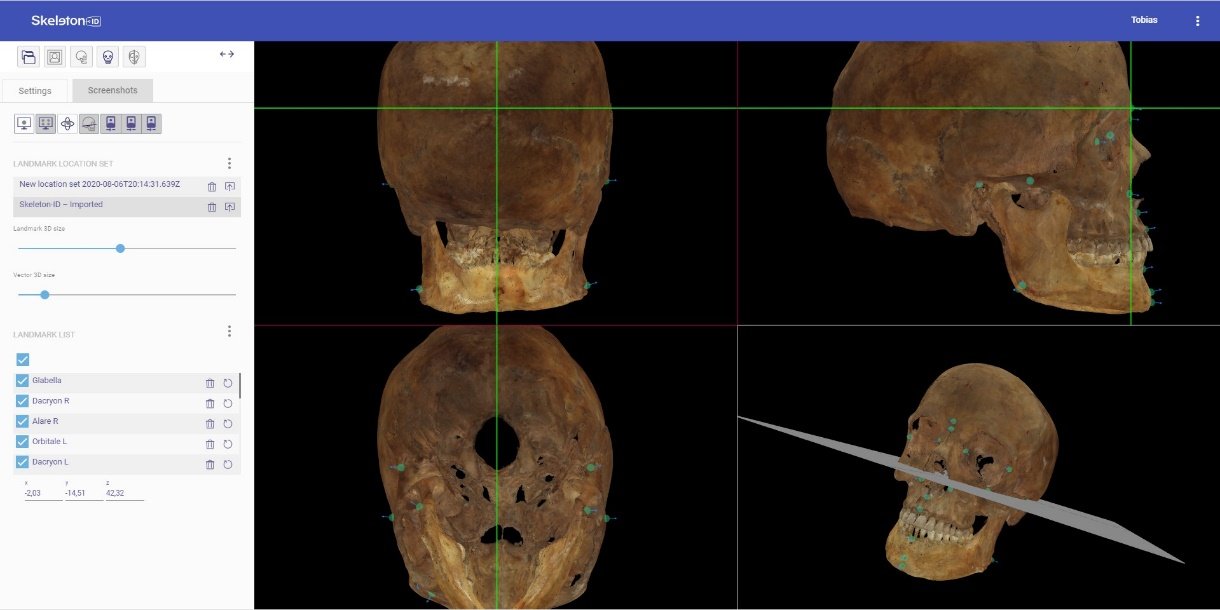 Fig. 8. (A) Norma Occipitalis; (B) Norma Lateralis (right); (C) Norma Basalis and (D) Free camera.
1We recommend reducing the 3D vector size to the minimum (1) for a better visualization of the craniometric points.
2With the flip button we can switch between the different cranial views.